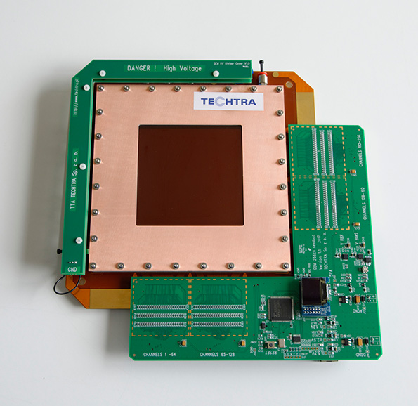
The electronic data acquisition system consists of a power supply, low-noise multi-channel charge-to-digital transducers, an FPGA that processes data and generates clock signals, and an Ethernet interface 100Mbit for communication with a PC computer . Currently, three versions of detectors have been developed: V1.0, V1.1 and the latest V2.0
The detectors in versions V1.0 and V1.1 are made with a 4-layer printed circuit in a L-shape. That shape is suitable for GEM detectors with an active area of 100 × 100 mm2 – the detector is directly plugged into X-Y readout strips via Panasonic connectors. Those detectors simultaneous gathers data from 256 channels (128 × 128 strips). The sampling frequency for V1.0 detector is 4 kHz, while for V1.1 version it is 6.25 kHz. Both versions works with a resolution of 20 bits. The detectors communicate with the computer via the 100Mbit Ethernet interface. The difference between versions is that the latest one has: a display showing the current status of a detector, measurement parameters and TCP / IP configuration; a digital potentiometer for remote setting of the bias charge of the detector input, and enables faster measurement by using a 16-bit data bus between the FPGA and the Ethernet module. The detector in version V1.1 is shown in Figures 1 and 2.


